
|
|
|
| Operating Systems Development Series | |
|
This series is intended to demonstrate and teach operating system development from the ground up. IntroductionWelcome! In this chapter we will cover something a bit more complex: The keyboard. We will learn about the keyboard itself, a little history lesson, keyboard internals, the 8042 and 8048 microcontrollers, and developing a keyboard driver. This will also be the first device that we will program within this series. Excited? We have already learned how hardware programming works and have experience in it; now it time to put it to the test. Ready? This is also the first device that we will be programming that not only requires us to work with one controller but two. These controllers communicate with each other and our system. To make things more complex, both controllers have their own set of commands and way to work with them. Because of this, this chapter is fairly detailed in a couple of places. This chapter also includes the first interactive demo: A basic command line parser. Excited? This is also the first chapter that we look at device drivers in more depth: The importance of hardware abstraction and device drivers. Heres the list:
Keyboard - HistoryBack in timeA keyboard is an input device that we use as a form of input to a computer. They were originally modeled off of a typical typewriter when they were first introduced. However the creation of the keyboard was not directly modeled from it. When the typewriter was patented in by Christopher Latham Sholes in 1877 several manufacturers and people further developed the original design. What evolved through a series of inventions was the Telegraph. Around this same time, inside of the 1930s, IBM was using Keypunches (punch card machines combined with typewriters) in their adding machines. Early computer keyboards adapted from both the keypunch and telegraph designs. The ENIAC (Electronic Numerical Integrator And Computer) was the first general purpose computer. The ENIAC used a punchcard reader as both an input and output device. in 1946. In 1948, the BINAC (BINary Automatic Computer) used an electromechanically controlled typewriter as both an input and output device. When does the keyboard evolve from these inventions? The computer keyboard that we all know does not evolve into what it is today until 1964 when MIT (with Fernando Corbató), Bell Laboratories and General Electric joined together to create the Multics (Multiplexed Information and Computing Service) machine. With the Multics, a new interface was at hand: They combined the technology of the cathode ray tube (CRT) used in televisions and electric typewriters to create a Video Display Terminal (VDT). The VDTs allowed a way for the users to be able to see what they were typing which made the computer alot more easier to work with. Over the course of the 1970s and 1980s almost all computers had a form of VDT technology and a form of an electronic keyboard for input. Through the years, CRT and LCD displays replaced VDT technology, and the electronic keyboard also became standard among all general purpose computers. Today, we use keyboards every time we go on a computer. Most of the keyboards layout still remains from the typewriter and the way it is used are the same. However, thanks to the new era of electronic devices keyboards now come in alot of different forms. From the generic plastic keyboards, keyboards the fold or have back lights in them, to even laser keyboards.Keyboard LayoutThe generic keyboard layout is known as a QWERTY keyboard because the characters QWERTY are the first five characters on a typical keyboard. The QWERTY layout was purposely designed during the typewriter era to slow down the typing speed of typists because of the original mechanical limitations of early typewriters. This was primarily to decrease the amount of time between each keypress and to give the print heads enough time so they do not jam. The QWERTY layout has been adapted in all keyboards to this day.Inside the keyboardWhat actually happens when you press a key on your keyboard? How can the keyboard tell the program what keys are down? The very text that is being read right now (thats right, me ;) has been input by keyboard. How can the keyboard do this? Lets take a look! Note: The exact details depend on the keyboards specific type and model. Because of this, I will only be covering a generic 102 key keyboard here.Opening the caseYou might be surprised by how keyboards came from being complex printed circuit boards (PCBs) to a single integraded board with its own microprocessor. If you were to open your keyboard, you might see something like this: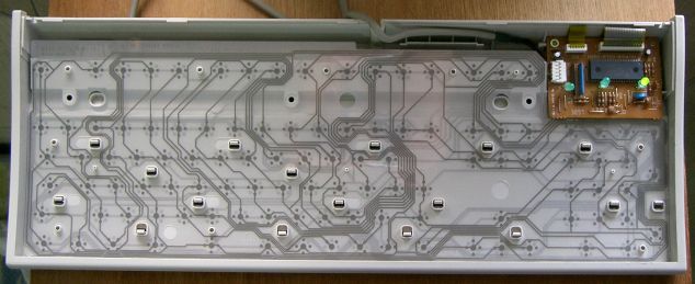 Keyboard EncoderThe microprocessor used by the keyboard is useually a form of the original Intel 8048, which just so happens to be also Intels first microcontroller. This controller is known as the Keyboard Encoder. The exact keyboard encoder used is very dependent on your keyboard. There are hundereds of different keyboard encoders but they all do basically the same thing. The rows and columns within the key grid are connected to 8 bit I/O ports on the keyboard encoder. When a key is down, the switch at that location within the key grid is closed which allows current to flow through it completing the circuit. This current enables the pin on the keyboard encoder of the correct ports that the key location corrosponds to. Thus, all the controller needs to do is scan its ports to see if a key is down or not by checking if a port line is active. If a key is down, the keyboard encoder looks up the location within its Read Only Memory (ROM) character map to see what the Scan Code is for that character and stores it in its internal 16 byte memory. The keyboards processor includes its own timer, 33 instruction set, and can even access 128K of external memory. Using its timer, it can determin if the key is down based on weather it is by user input or a bounce. If a bounce happens, it will useually be much faster then any human can input. If the key is still down when its timer reaches 0, it is reset and the character is inserted into its internal 16 byte buffer. It is important to note that there are two keyboard controllers that we can communicate with: The keyboard encoder inside of the keyboard and the keyboard controller inside on the motherboard. We will look at the other controller a little later, don't worry ;) For now, keep in mind that their are two controllers, and the keyboard encoder is one of them. The keyboard encoder communicates with the system through a method defined by the keyboard protocol. Lets take a look.Keyboard ProtocolThe keyboard encoder sends data as bytes to the motherboards onboard keyboard controller. The way it is sent depends on the protocal used by the keyboards interface. This is useually a 5-pin DIN connector, 6 pin Mini-DIN connector, USB connector, SDL connector, or wireless using an infired (IR) interface. The 5 pin DIN connector used for AT/XT keyboards normally is on the back of the computer and looks like this:
1: Clock 2: Data 3: N/A 4: Ground 5: Vcc (+5V) 
1: Data 2: N/A 3: Ground 4: Vcc (+5V) 5: Clock 6: N/A 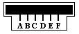
A: N/A B: Data C: Ground D: Clock E: Vcc (+5V) F: N/A Keyboard ControllerThe keyboard controller used inside of the system case is useually a form of the original 8042 keyboard controller. The keyboard controller interfaces with the keyboard encoder through the keyboards protocol and provides a way to interface to it. On most newer systems, the keyboard controller is not a separate integrated circuit (IC) but rather part of the motherboards Super Input/Output (IO) controller that also houses the floppy disk controller (FDC), parallel port interface, serial port interfaces and mouse interface. Most newer systems super IO controller uses the Low Pin Count (LPC) bus rather then Industry Standard Architecture (ISA) on the southbridge of the motherboard.Scan CodesA Scan Code is a data packet that represents the state of a key. If a key is pressed, released, or held down, a scan code is sent to the computers onboard keyboard controller. There are two types of scan codes: Make Codes and Break Codes. A Make Code is sent when a key is pressed or held down while a break code is sent when a key is released. There is a unique make code and break code for each key on the keyboard. The entire set of numbers that represent all of the scan codes make up the keyboards scan code set. There are generally three different scan sets that the keyboard can use. However there is no easy way to determin what scan set it uses as the scan values are random. Because of this, you will need to use a lookup table to determin the key the scan code represents. Lets take a look at the scan code tables. Note: These tables are important! We will need to use these to determin what keys are pressed on the keyboard. Also note: All scan codes in these tables in are hexidecimal. These are fairly large tables so I decided to put them as a separate resource. Please see the tables in the resources section here. Lets have an example. If you press shift+A keys on your keyboard, what will be the make code sent to your computer? In order to better understand this, lets take a look at the sequence of events that happens. First the shift key is pressed, then the A key is pressed. Then the A key is released followed by the shift key being released. Assuming that the scan code set is the default scan code set for modern keyboards, the left shift key make code is 0x12, break code is 0xF0 and 0x12. The make code for the A key is 0x1C while the break code is 0xF0 and 0x1C. So when this event occurs, the following scan codes will be sent to the computer:Looking at the above, we can see that the scan codes sent will be 0x12, 0x1C, 0xF0, 0x1C, 0xF0, and 0x12. If you press a key and hold it, the key becomes typematic. In other words, the keyboard will keep sending the keys make code until the key is released or another key is pressed. Try it: Open up your favoriate text editor and hold down a key. After a short delay another of the same character will appear followed by a long series of the character. The typematic delay determins the amount of seconds to wait before entering typematic mode, and the typematic rate determins the amount of character make codes per second to send to the computer. During typematic mode, the character data is not buffered. If multiple keys are held down, only the last key held becomes typematic. Scan codes are very important to us. When a scan code is sent to the onboard keyboard controller, the keyboard controller stores the scan code into its internal memory. The keyboard controller then toggles its Interrupt Request (IR) line to high. If the interrupt line is not masked by the Programmable Interrupt Controller (PIC) then this will cause IRQ 1 to be fired. Even if the IRQ is masked, because the read buffer can be read by us through software, we can read the scan code and determin what key was just released or pressed. Keyboard Interface: Developing a Device DriverWe have covered alot already in this chapter. We have looked at the history of the keyboard as in interface device, the QWERTY keyboard layout, and looked at the inside of the keyboard to see how it works and the primary components that make it work. We have also looked at scan code sets and the keyboards protocols. Don't worry if you do not understand everything yet, we will look at everything in more detail within the next couple of sections. We will also be developing device driver for our keyboard as well. Cool, huh? All of the code in this section will also be in the final demo.Keyboard Interfacing: PollingRemember from the previous section that there are two controllers when working with the keyboard? That is, there is the Keyboard Encoder inside of the keyboard as well as the Keyboard Controller on the motherboard. This is the first chapter in the series where we need to interface with several different controllers to control a single hardware device. Thats right: We can communicate with both of these controllers. Well, kind of. When we send a command to the keyboard encoder, we still send it to the onboard keyboard controller however it reroutes it to the keyboard encoder over the keyboard protocol. Okay, so we can communicate with both controllers. How fun is that? Knowing that both controllers work with each other, they also communicate with each other. The keyboard encoder may send alot of different codes to the onboard keyboard controller to store. These can be scan codes or error codes. This allows us to also recieve information from both the keyboard encoder and onboard controller. All of this communication is done by simply using the IN and OUT instructions to read or write to the controller ports mapped in the IO address space. While we never had to worry what these ports are, understanding how IO mapping works with controllers becomes more important here. This is one way we can interface with the keyboard: We can manually communicate with the controllers to check if a key is down, up, or what not. This is known as polling the keyboard. This is how we are able to get the last scan code from the keyboard: by polling the keyboard controller for it.Keyboard Interfacing: Interrupt Request (IRQ)Remember from the PIC tutorial that the keyboard controller can be configured to use an interrupt line? We can configure the keyboard controller to issue IRQ 1 whenever a key has been pressed or released. This is the most common way to interface with the keyboard. Whenever IRQ 1 is fired, you should always test to see if a scan code has actually been sent to the keyboard controller. This is done by polling the keyboard controller to get the last scan code.Detail: 8042 Keyboard Microcontroller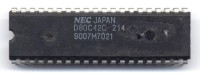 The original 8042 Microcontroller 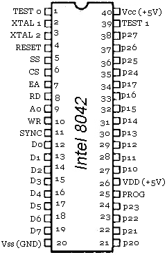 Port MappingIn the i86 architecture, the following ports are used to communicate with the keyboard:
We will not be going over the routines used to interact with these controllers just yet as it requires some knowledge of the commands of the controllers. RegistersStatus RegisterThis might look familiar from When we covered enabling the 20th address line. To read the status register, simply read from I/O port 0x64. The value returned is an 8 bit value that follows a specific format. The format is a little different depending on the mode of the controller. Here it is again. I bolded the important ones:
Great! So, all we need to do is to read from the keyboard controllers status register at port 0x64. Then test whatever bit we want to check the status of it based on the bit masks above. So, to read from the keyboard controller status register, all we need is:
Reading and writing: Input bufferTo send a command, we first wait to insure the keyboard controller is ready for it. This is done by seeing if the input buffer is full or not. We test this by reading the keyboard controllers status register and testing the bit. If its 0, the buffer is empty so we send the command byte to it. (Remember all of this information is inside of the status register bit layout shown above.)The keyboard encoder is very simular as you can see below. Remember that commands sent to the keyboard encoder are sent to the keyboard controller first. Because of this, you still need to insure the keyboard controller itself is still ready for the command.
Keyboard Encoder CommandsWhen writing a command byte to port 0x60 the keyboard controller transmits the value directly to the keyboard encoder. The following is a list of the command bytes:
Command 0xED - Set Light Emetting Diods (LED's)This command is used to set the LEDs on the keyboard. The next byte written to port 0x60 updates the LEDs on the keyboard and follows the format shown below:
Command 0xF0 - Set alternatate scan code set (PS/2 Only)This command sets the scan code set to use. The next byte written to port 0x60 must be a byte of the following format:
Command 0xF3 - Set autorepeat delay and repeat rateThis command sets the autorepeat delay and repeat rate. Next byte written to port 0x60 must be the following format:
Return CodesAs you know, the keyboard encoder communicates with the systems onboard keyboard controller. Most of the values returned will be a scan code but sometimes it may also return an error. These values are sent from the keyboard decoder to the system through port 0x60. The returned value can be one of the following:
Onboard Keyboard Controller CommandsSome of these commands we have already seen in the A20 chapter. Alot of the commands listed here are new however and some are very low level. That is, some of these commands allow you to control specific lines connected to the controller. This is why I had to cover the controller's lines and how it interfaces with the keyboard device. Other commands allow you to read or write to the controllers internal RAM.
Command 0x20 - Read Command Byte and reading controller RAMLook at the table above. Notice that the commands 0x20 - 0x3F is used to read the controller RAM? And yet, command 0x20 is used to read the command byte also. What is going on here? Actually, they both refer to the same thing. The command byte is stored within the controllers RAM. So, when reading the command byte, you are reading from the controllers internal RAM. Cool? When reading from the controllers RAM, the last 6 bits of the command refer to the the location within RAM to read from. On certain MCA systems, you have access to all 32 locations within the RAM. On other systems, you can only access the bytes at 0, 0x13-0x17, 0x1D, and 0x1F. These locations are:
Command 0x60 - Write Command Byte and writing controller RAMThe command bytes 0x60 - 0x7F are very simular to the above and allows you to write to the same RAM locations as described above. the more important one is reading byte 0 of the controllers RAM (The command byte, remember?) which can be done by sending command byte 0x60. Along with the above command, there is no routine written for this command for the end demo.Command 0xAA - Self TestThis command causes the controller to perform a self test. It returns the result in the output buffer that can be read through port 0x60. It returns 0x55 if the test passed successfully, or 0xFC if it failed. Here is an example routine. Notice how it first sends the KYBRD_CTRL_CMD_SELF_TEST command (command 0xAA) to the keyboard controller. Afterwords, it waits for the keyboard controllers output buffer to be filled with data. This will tell us if the test completed or not. When it completes, it returns true (test successful) if the result in the output buffer is 0x55, or false (test failed) otherwise.
Command 0xAB - Interface TestThis command causes the controller to test the serial interface between the controller and the keyboard. The result of the test is placed in the output buffer that can be read on port 0x60. The result can be one of the following:
Command 0xAD - Disable KeyboardThis command causes the controller to disable the keyboard clock line and set bit 4 (keyboard enable) of the command byte. Please see the Read Command Byte section for the format of the command byte. In other words, this command disables the keyboard. It is a good idea to store the current state of the keyboard so that your system can keep track of the current status of the keyboard. This is done in the demos keyboard driver through _kkybrd_disable.
Command 0xAE - Enable KeyboardThis command causes the controller to enable the keyboard clock line and clears bit 4 (keyboard enable) of the command byte. Please see the Read Command Byte section for the format of the command byte. In other words, this command enables the keyboard. Here is an example routine taken from the demo. Notice how easy this one is :)
Command 0xC0 - Read Input PortThis command reads the input port (lines P10-P17 on the controller) and copies the binary value to the output buffer that can be read through port 0x64. Because we have not looked at the lines that this port has, lets look at it now:
Command 0xD0 - Read Output PortThis command tells the controller to read from its output port (P2) and place the result in the output buffer at port 0x64. By reading from port 0x64 after issuing this command, we can check the bits of the controllers output port. The controllers output port is just the P20-P27 lines of the controller (Remember this from before?). The binary value on these lines are then stored into the output buffer when this command is executed. We have not covered the output port pins and what they are yet. (Well, actually we have in the A20 chapter, but not in detail) so lets look at it here:
Command 0xD1 - Write Output PortThis command copies the byte from the output buffer (port 0x60) and places the byte on the controllers output port lines. Please see the previous section (Read Output Port Command) for a description of these lines. For the most part, you would want to bitwise OR specific bits that you would like to change and keep everything else unchanged to prevent possible problems. This command is useful in several ways. It allows you to enable or disable the IRQ used by the controller, enable or disable the A20 gate, or even reset the system by setting bit 0. Again, please see the previous section for the list of the bits that can be changed.Command 0xE0 - Read Test InputThis command copies takes the binary value from the test port lines on the controller and places them in the output buffer so they can be read through port 0x60. The test port are the lines TEST 0 and TEST 1 of the microcontroller (please see the controller pinout diagram in this chapter). Because we have not covered them yet, lets take a look:
Command 0xFE - System ResetCauses the controller to pulse bit 0 of the controllers output port (pin P0) which resets the CPU. This basically does the same thing as sending the Write Output Port command resetting bit 0. Send this command if you would like to reset the system in a nice way.Keep in mind that this may not work on all systems. An easy way to see if it works or not is to see if your program is still executing after the above routine :) Demo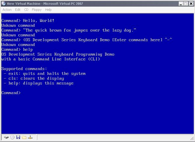 The first interactive demoDEMO DOWNLOAD
Keyboard: Piecing it TogetherWe have looked at some of the routines from this demos keyboard driver already. We looked over communicating with the keyboard encoder and controller; and even routines for several different important functions for enabling, disabling, testing, LED updating, system reset, and more. This is great, but we are missing a few important details that tie everything together. Lets take a look, shall we?Keyboard: Storing the current stateAs you know, you can press any of the keys on your keyboard at any time. Because of this, there needs to be a way to scan each key to see if they are down or not. The good thing here is that the keyboard encoder already does this! To make things more easier, the keyboard encoder sends the scan code directly to the onboard keyboard controller which in turns invokes IRQ 1. As long as IRQ 1 is not masked, we can install our own interrupt handler at IRQ 1 so that we can get notified whenever a scan code is sent from the keyboard encoder. What does this mean? Our interrupt handler will be invoked any time a scan code is sent to the keyboard controller. This can happen at any time. Because of this, we need to somehow determin what the scan code is inside of the handler by polling the keyboard controller for it. However, we may want to do different things if a key is down (like the caps lock or num lock keys). These keys supposed to stay on or off when they are pressed. Then, what about other keys like shift? These keys must be held down and released when the key is released. Because of this, we need to come up with a method of storing the current state of these keys and the last scan code read so that they can be retrieved again later after the IRQ has already returned. This can be done by storing the current state in a few global varables or a structure and simply using them.Keyboard: Interrupt HandlingThis one is important. Remember that, for each key stroke and key release several bytes (The scan code) is sent to the keyboard controller? When this occurs, the keyboard controller signals the Programmable Interrupt Controller (PIC) to generate IRQ 1. Yes, dear readers, this in turn causes the PIC to execute our keyboard interrupt handler. The purpose of the interrupt handler is to update the current state of the driver and to decipher the scan code by converting it to a format that can be used by the driver and the system. Yep, thats all that is to it ;) The interrupt handler is what ties everything together. It is a little big so I decided to not put it in this text, however I urge everyone to take a look at it to see how it works.Keyboard: InitializationRemember that the keyboard controller is connected indirectly to the programmable interrupt IRQ 1 line? Because we mapped the IRQs using the PIC to start from interrupt vector 32 (IRQ 0), IRQ 1 is at interrupt vector 33. Because of this, we need to install our interrupt handler using our setvect routine to use interrupt vector 33. Everything else is pretty simple. We simply clear out the current driver state (stored as globals) and clear the LEDs using our kkybrd_set_leds routine.
ConclusionThats it for this chapter! The system is starting to get interesting, don't you think? We can possibly expand on this demo to make it actually useful to an extent, which is nice. However, we are rather limited in what we currently can do. Wouldn't it be useful if we can run other programs to do our work for us? Or even to load other files from disk? While abstracting a complete filesystem structure is very complex topic; we can, however, focus on loading files from a single disk. However, we run into a problem. In order for us, at the minimum, be able to load a file from disk we have to program the Floppy Disk Controller (FDC) first. This is the topic for the next chapter. Hope to see you there! :)Until next time,
~Mike | ||||||||||||||||||||||||||||||||||||||||||||||||||||||||||||||||||||||||||||||||||||||||||||||||||||||||||||||||||||||||||||||||||||||||||||||||||||||||||||||||||||||||||||||||||||||||||||||

